GIGABYTE X99-Gaming G1 WIFI Motherboard Review
by Ian Cutress on December 18, 2014 10:00 AM ESTDue to the level of consistency between BIOSes and software packages within the same chipset from the same company, our overview of the X99-Gaming G1 WIFI almost mirrors the one of the X99-UD7 WIFI package that we reviewed during the launch of X99.
GIGABYTE X99-Gaming G1 WIFI BIOS
For X99, several things have changed for the BIOS. The classic mode gets a facelift and moves to a cleaner but blockier interface with a good contrast between text and background. In the HD mode, the text now all fits in the boxes and there is some improvement to adjust the visual differentiation between background and text, but more could still be done. Interactivity is still quite minimal, with classic and HD mode featuring many of the same options slightly rearranged.
The first entry screen is the Startup Guide which is the main recipient of text adjustment, but we also get a few more options to fill up this 3x3 grid.
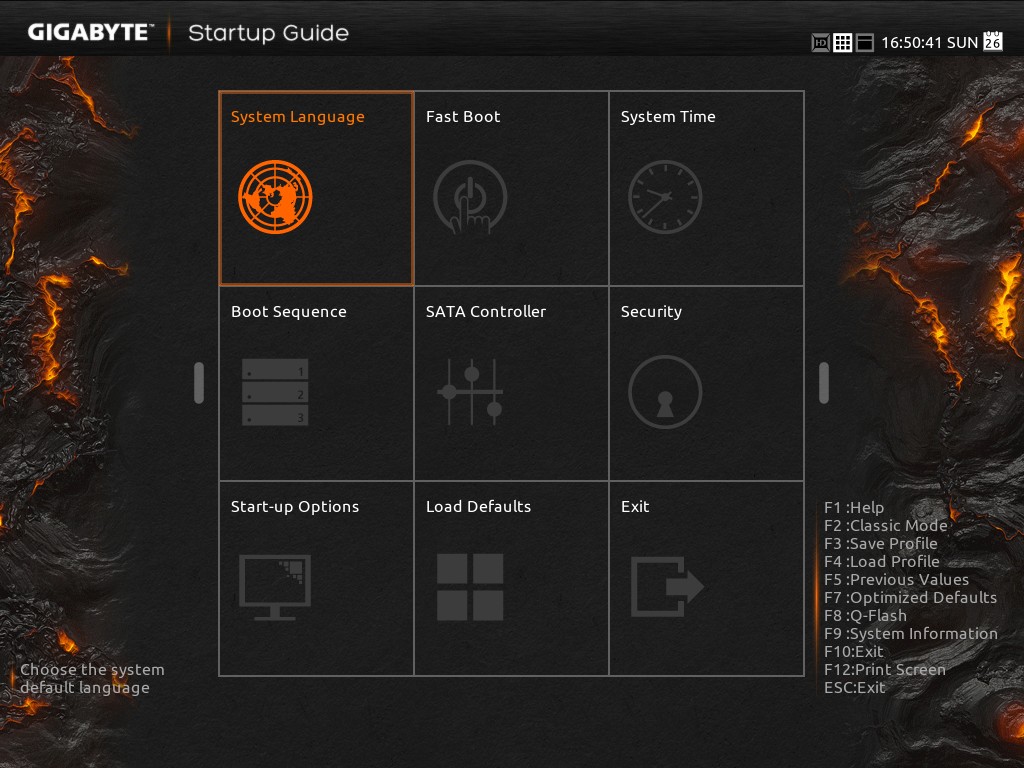
Most of these are self-explanatory. Fast boot gives options related to Windows 8 such that devices are not initialized until later in the OS boot process, speeding up overall POST time:

The SATA controller option text now all fits nicely into each of its boxes, although due to the dual AHCI controller nature of the chipset and only six SATA ports having access to RAID, it does not help the user much if the drives are plugged in the wrong ports:

Ideally we would see an explanation giving SATA versus sSATA ports on the motherboard used, and what drives are installed where.
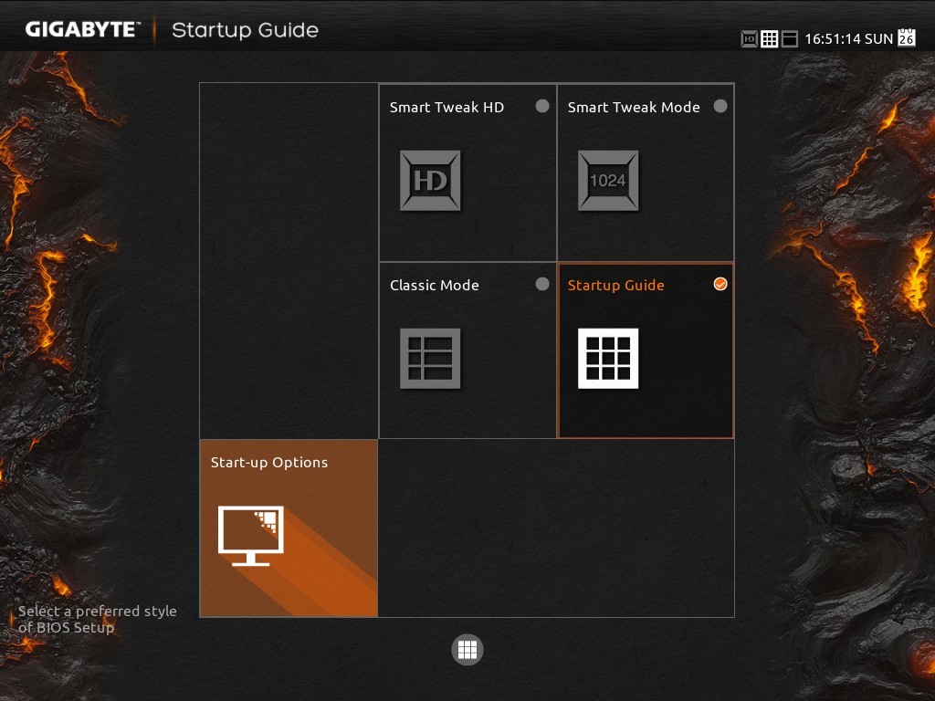
The Startup Options allows the user to boot into any of the four modes available. The HD mode does offer a smaller sized version with less information if the monitor is not capable of 1920x1080.
Despite a nice start guide for users, it would help if the initial screen detailed the system, perhaps in the top left. We want to see the name of the motherboard, the BIOS used, the CPU installed, the DRAM installed and frequencies where possible. That way any user trying to debug the system without having access to the insides will be able to see immediately what is at hand.
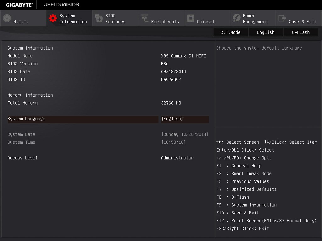
The standard classic mode gets an update from the blue interface to a sleeker grey and white menu system. The layout is pretty much the same as before, along with the information provided. For example, the entry point offers the model name of the motherboard and the BIOS version, but no mention of the CPU installed.
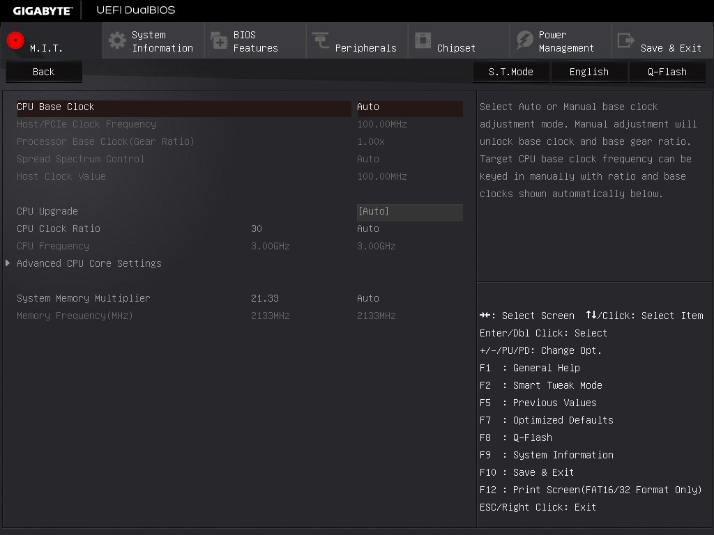
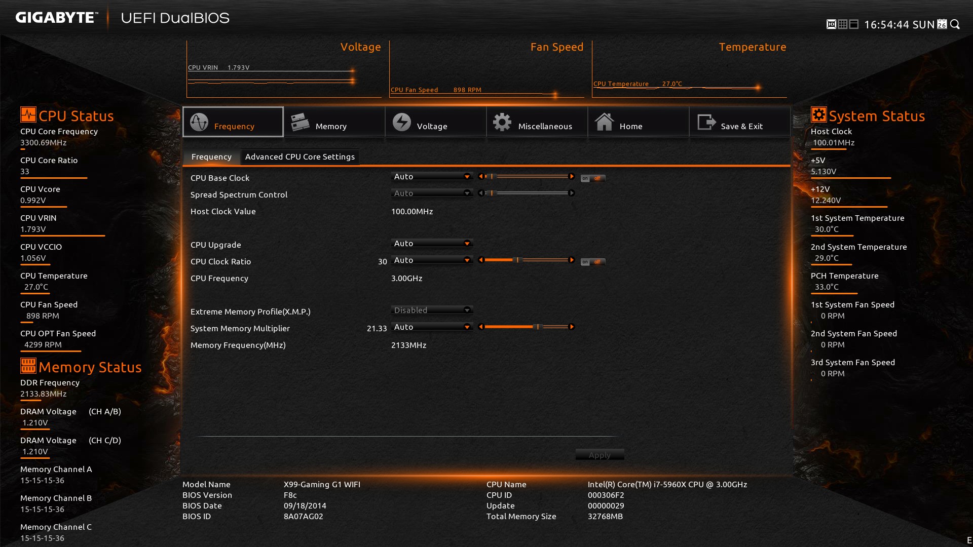
The overclocking options in the GIGABYTE BIOS are only for manual overclocking, and split into several sub-menus coming from MIT. The Frequency menu allows the user to adjust the CPU and DRAM:
In order to adjust the per-core ratios or the Uncore and C-states, the CPU Core Settings menu is provided:
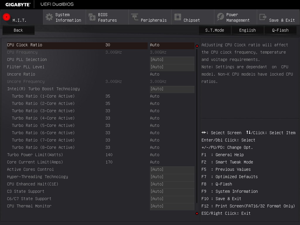
Note that there are no voltage options in either of these menus. GIGABYTE’s reasoning is that the voltage options are solely for the voltage menu, but I differ. Motherboard manufacturers can place the same option in multiple menus, but often choose not to for reasons of layout or space or to avoid confusion. I do not see that as an issue – if anything, I believe it would enhance the experience especially for an enthusiast wanting to adjust these settings. So while the voltage settings are not duplicated, the DRAM frequency strap is – we see it here in the Advanced Frequency menu and also in the Advanced Memory menu:
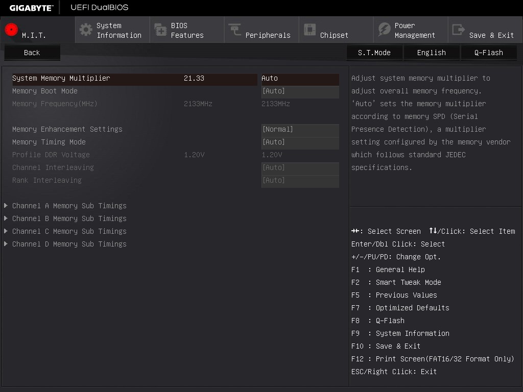
It makes no sense to duplicate this option and not others.
In order to adjust sub-timings for the memory, as with previous GIGABYTE motherboards, the memory timing mode must be changed to ‘Manual’ to set a rule for all modules or ‘Advanced Manual’ to set per-module timings.
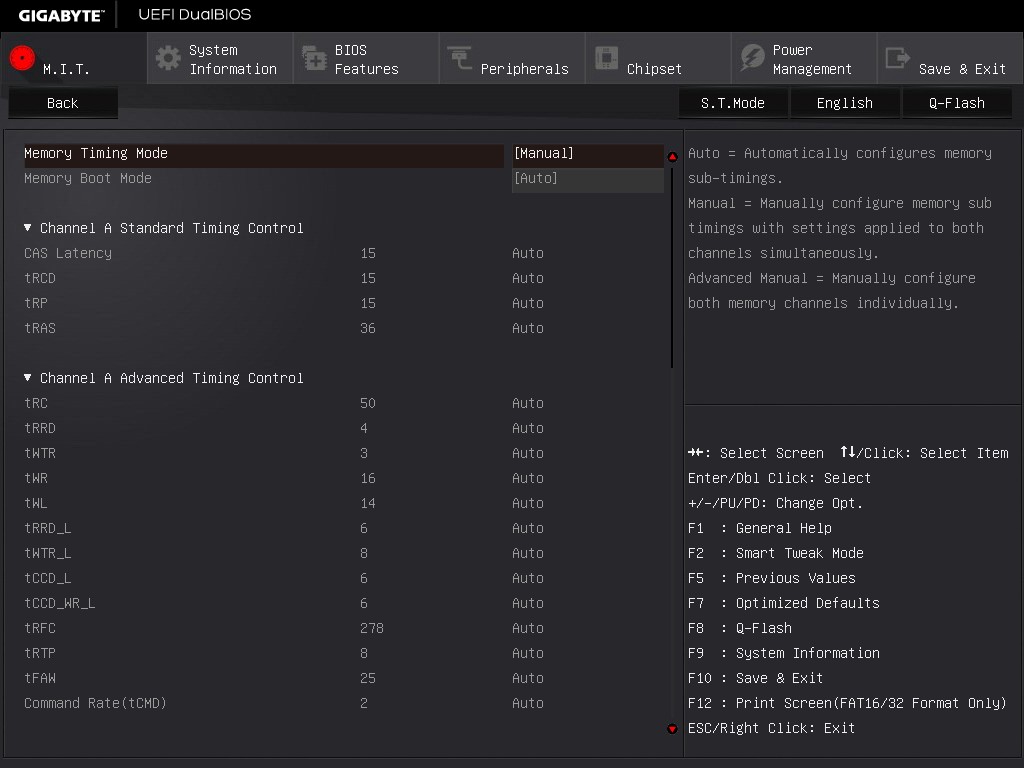
GIGABYTE has adjusted how the BIOS communicates what each option means to the user in the top right of the screen. I remember one of my contacts at GIGABYTE was writing the initial drafts for these info texts earlier in the year, and remarking that it was no small feat especially after several iterations and then sending it to the translators for other languages and making sure no subtleties were lost.
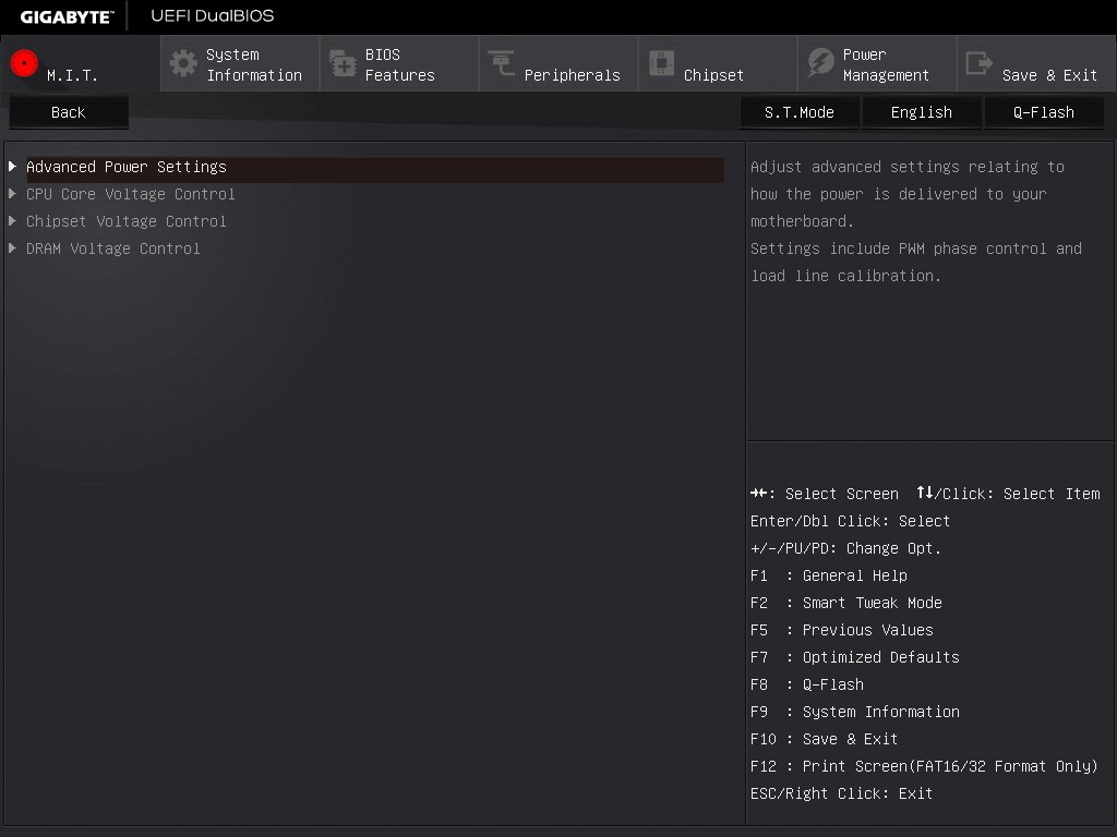
The Advanced Voltage Setting menu is split into several sub-options.
The Power Settings menu is for voltage protection options, current protection and switch rate adjustment. The most important option though is the Load Line Calibration for the FIVR:

As mentioned in the help text, the top setting will maintain 100% voltage at load to combat the regular voltage drop across the processor as the workload varies.
The Core Voltage menu is where the meat of the CPU voltage options are:
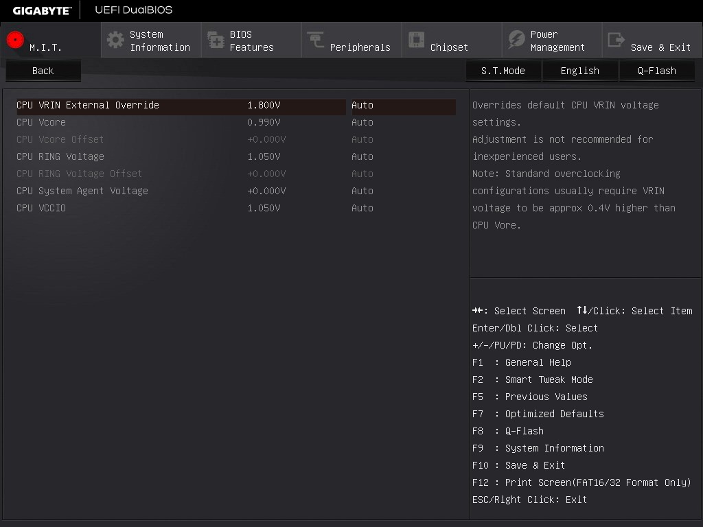
Adjustments to the VRIN (FIVR), VCore and Cache voltages are here, with only absolute values allowed. Other manufacturers offer both offset and absolute choices for these values although I find offset values more applicable for automatic overclocking options.
The fan controls in the classic mode are in the PC Health option from the MIT tab.
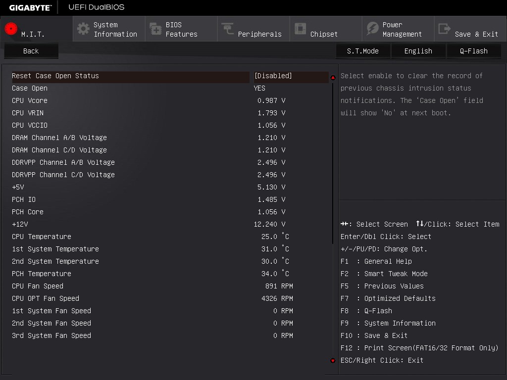
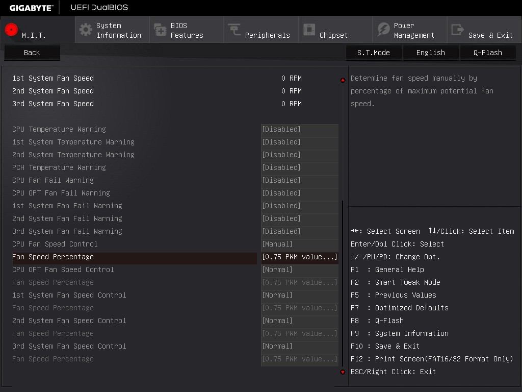
While the system has four temperature sensors and five fan headers, the level of fan speed options in the BIOS is very basic.
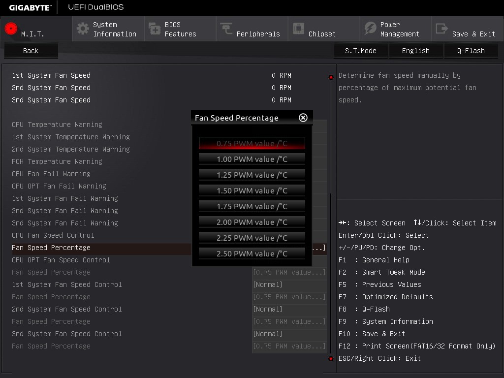
For anyone not used to a value describing how one variable adjusts with another, the options here might make no sense. The power applied to a fan is a ‘PWM’ number from zero to 255. GIGABYTE’s options allow you to adjust that value based on the temperature, in terms of ‘PWM per ºC’. So a CPU temperature of 50ºC at 2 PWM per ºC will give a value of 100, which means that 100/255 = 39.2% of the full power of the fan is used. To confuse the matter even more, a fan does not respond linearly to power increases, and GIGABYTE does not mention of this value has a base number.
Other manufacturers have the fan controls in the BIOS at a state where they are a lot easier to follow, and GIGABYTE has fallen behind in adapting their controls to a more interactive interface that is easier to understand.
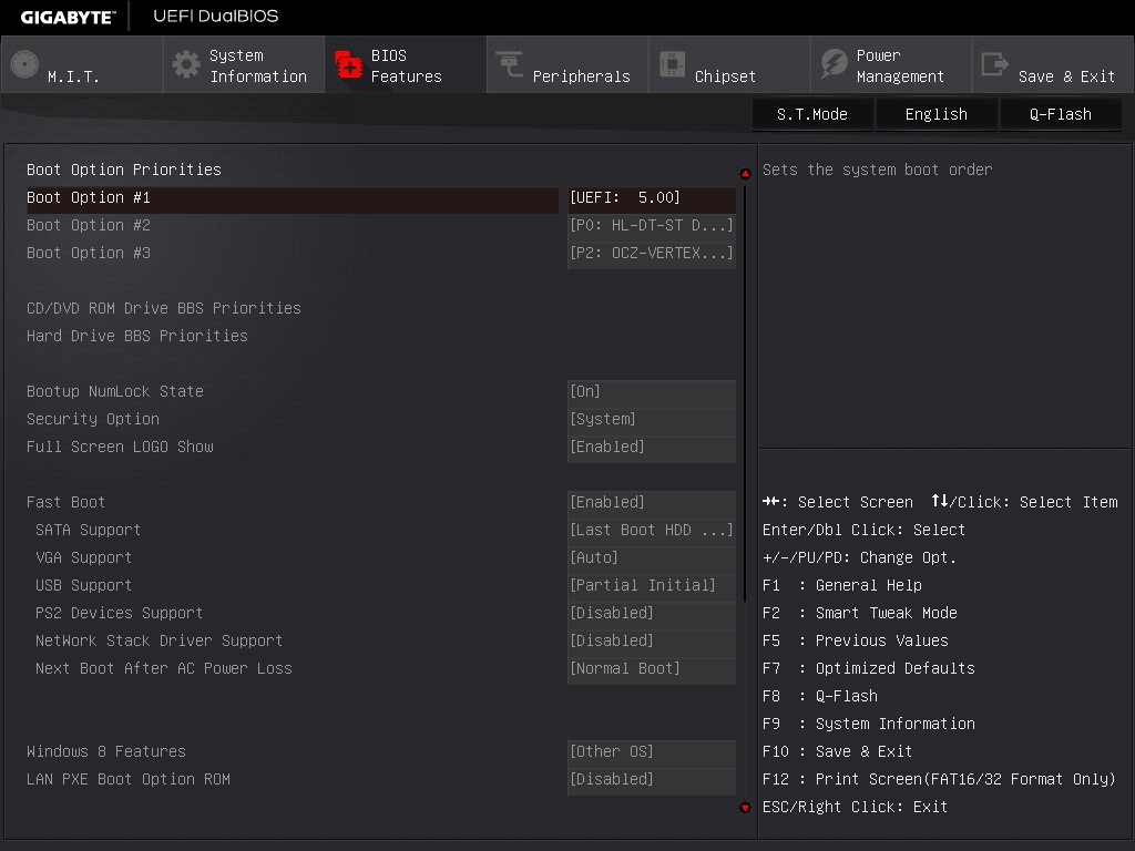
The BIOS Features tab relates to the boot order and fast boot options:
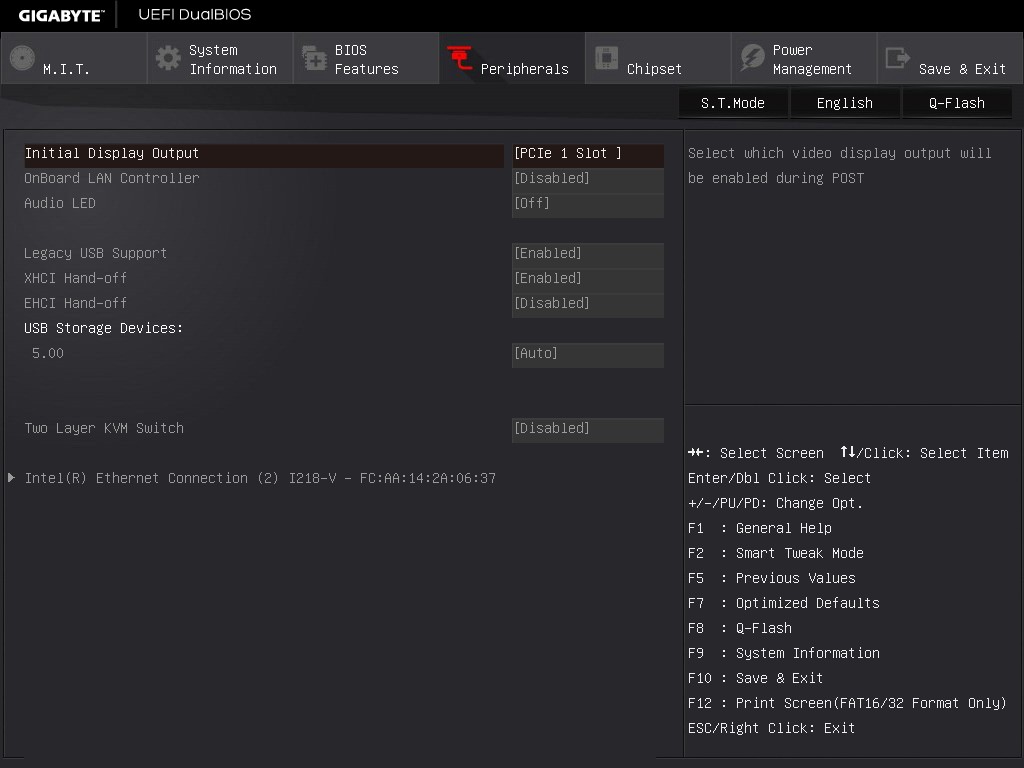
The Peripherals tab involves LED options, enabling onboard controllers and an interesting option relating to KVM switches:
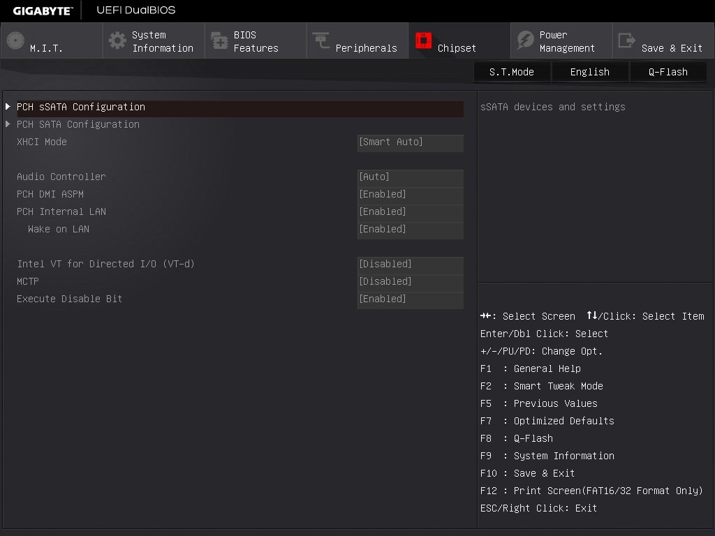
The Chipset tab is for SATA adjustments, with GIGABYTE offering different menus for the sSATA (non-RAID) and SATA (RAID) AHCI controllers:
The rest of the classic BIOS allows for power management and BIOS flashing, with the Save and Exit menu giving boot override possibilities.
The full HD mode uses a similar sort of option arrangement in the middle of the screen with as much information as you can pack into the surrounding edges. Most BIOSes need something like this around the edge to tell the user about the system, although I might suggest that having bars underneath values such as ‘CPU VRIN’ are ultimately not necessary and could be cleaned up. The ideal BIOS is one that displays everything succinctly without wasted space but still visually effective. For example, perhaps graphing the voltage change over time in the BIOS is not particularly helpful.


16 Comments
View All Comments
Meegul - Thursday, December 18, 2014 - link
The aesthetic of the motherboard would be nice. That is, if it weren't for those green capacitors by the audio chip. Seriously, with a good looking red and black motherboard, what is such a color doing on it? Otherwise, it looks like a pretty good motherboard, albeit a bit pricey even for an X99 motherboard.chizow - Thursday, December 18, 2014 - link
They're colored that way because Nichicon makes them that way and has for years. Audiophiles who know the difference will notice this immediately and prefer this over a black or red tinned version.https://www.google.com/search?q=nichicon+audio+cap...
Unfortunately for this board, the Nichicon audio caps aren't enough to save the lackluster sound output, which ends up sounding extremely low bitrate and crushed/dumpy at higher output levels (adjusting input load level does not help).
If you have a few add-in boards installed, chances you don't see these caps anyways.
stux - Thursday, December 18, 2014 - link
[img]http://www.hardwareheaven.com/reviewimages/gigabyt...[/img]leetruski - Friday, December 19, 2014 - link
Those look like electrolytic capacitors rather than solid state. Is there a particular reason as to why they would have gone with those? Seem kind of out of place on a premium board.JeffFlanagan - Friday, December 19, 2014 - link
>Unfortunately for this board, the Nichicon audio caps aren't enough to save> the lackluster sound output
Who's still using onboard sound output? Audiophiles will use the USB DAC-UP ports to attach a nice external DAC, and the rest of us are using HDMI audio. A motherboard is about the worst place possible to encode audio due to all the electrical noise from the rest of the MB.
Stuka87 - Thursday, December 18, 2014 - link
The board looks nice, and has a ton of great features (3 year warranty is nice). Although I really question the built in wifi on a gaming board. Wifi is terrible for gaming. Random latency spikes make online gaming an aggravating experience.Morawka - Thursday, December 18, 2014 - link
ever heard of wifi direct? you'll need it for xbox one controllers, Nvidia shield controllers, etc..there are tons of wifi direct hardware on the market nowadays.
imaheadcase - Friday, December 19, 2014 - link
So? Still does not change the fact wifi is terrible for gaming.chizow - Friday, December 19, 2014 - link
I think the point is, its not either/or, it can be both. You can always hardwire your ethernet connection and use the wifi direct for connecting peripherals that use it for the best of both worlds...aliquis - Monday, March 5, 2018 - link
Hi Morawka.I just want to know how that WiFi Direct Connection using your Xbox One or Nvidia Shield controller is working for you ...
Even if it worked with any wireless card which the later doesn't do AFAIK and likely not the former either the Nvidia Shield one also need to have an Nvidia graphics card so it's complete garbage.
It's disturbing Valve doesn't have Steam controller support built in in their Steam Link =P