GIGABYTE X99-Gaming G1 WIFI Motherboard Review
by Ian Cutress on December 18, 2014 10:00 AM EST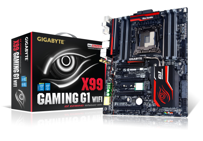
The gaming motherboard range from a manufacturer is one with a lot of focus in terms of design and function due to the increase in gaming related PC sales. On the Haswell-E side of gaming, GIGABYTE is putting forward the X99-Gaming G1 WiFi at the top of its stack, and this is what we are reviewing today.
One of the main points not noted to most end-users is that while a large company like GIGABYTE delivers many different product areas, such as motherboards, graphics cards, server products or gaming peripherals, each of these areas is a separate business unit within the company. Each business unit works somewhat independently from the rest, with their own marketing, sales and design departments. This system sometimes falls afoul when there a product areas designed to work together or share similar traits, such as the motherboard BIOS team and the server BIOS team that are essentially working on similar frameworks but completely independently. When it comes down to end-users and in particular the big growth segments in home computing such as gaming, both the motherboard business unit and the graphics card business unit should ideally work together to build the company brand. This was in progress with our last GIGABYTE gaming motherboard review, but finally seems to have been cemented with X99.
GIGABYTE X99-Gaming G1 WIFI Overview
There's no such thing as feature overload when it comes to motherboards, but the X99-Gaming G1 WIFI comes close. At times we have remarked certain motherboards for being expensive due to their features and not every owner would use them, but in the case here we can see most if not all being applicable to most users. Features can fall into two bins - passive, such that they work independently of any use, and interactive, such that they require the user. There being plenty of both here:
Passive:
- PowIRStage ICs with Cooper Bussmann chokes
- 30-micron gold socket and DRAM/PCIe slots
- LED lighting for audio path and back panel
- Gold plated audio ports
- AMP-UP with PCB separation
- Double-distance screw mounting holes
- Larger Heatsink Design
Interactive:
- 4-way GPU support
- M.2 SSD
- M.2 WiFi
- Sound Core 3D Audio Codec
- Dual Killer and Intel Network arrangement
- Upgradeable OP-AMP
- DAC-UP USB Ports
- SATA Express
- Software Package
- Q-Flash Plus USB
- 12 USB 3.0 ports (2 PCH headers for 2 each, 8 via Renesas hubs)
We will cover almost all of these throughout the review, but on top of this is support for up to 64GB of 1Rx8 RDIMM modules, ten SATA 6 Gbps ports (two are shared with M.2/SATAe), an onboard CPU overclocking button, a Thunderbolt add-in card header, five fan headers and voltage measurement points for extreme overclockers. All of this is bundled in the E-ATX (305mm x 259mm) form factor.
The BIOS and software packages are similar to those we saw on the GIGABYTE X99-UD7 WIFI we reviewed back at launch, which means plus points for the software but the BIOS is held back a little due to the HD mode being harder to read and gauge. Our issues with audio similar to that on the X99-UD7 WIFI appeared again, although it only seems to affect our quantitative testing software more than quality. The system uses Sound Core 3D rather than Realtek as well.
Performance has a number of plus points over previous X99 motherboards including power consumption and faster POST times. The near 100 microsecond DPC Latency is also a plus point. Due to its lack of MultiCore Turbo on the BIOS we tested, it falls behind at stock on some CPU benchmarks but automatic overclocking to 4.1 GHz makes that relatively painless.
At $340 on Newegg at the time of writing, the Gaming G1 WIFI sits in that $280-$360 mire between the low and high end X99 offerings but it makes a good stand with plenty of onboard features to help prove its position.
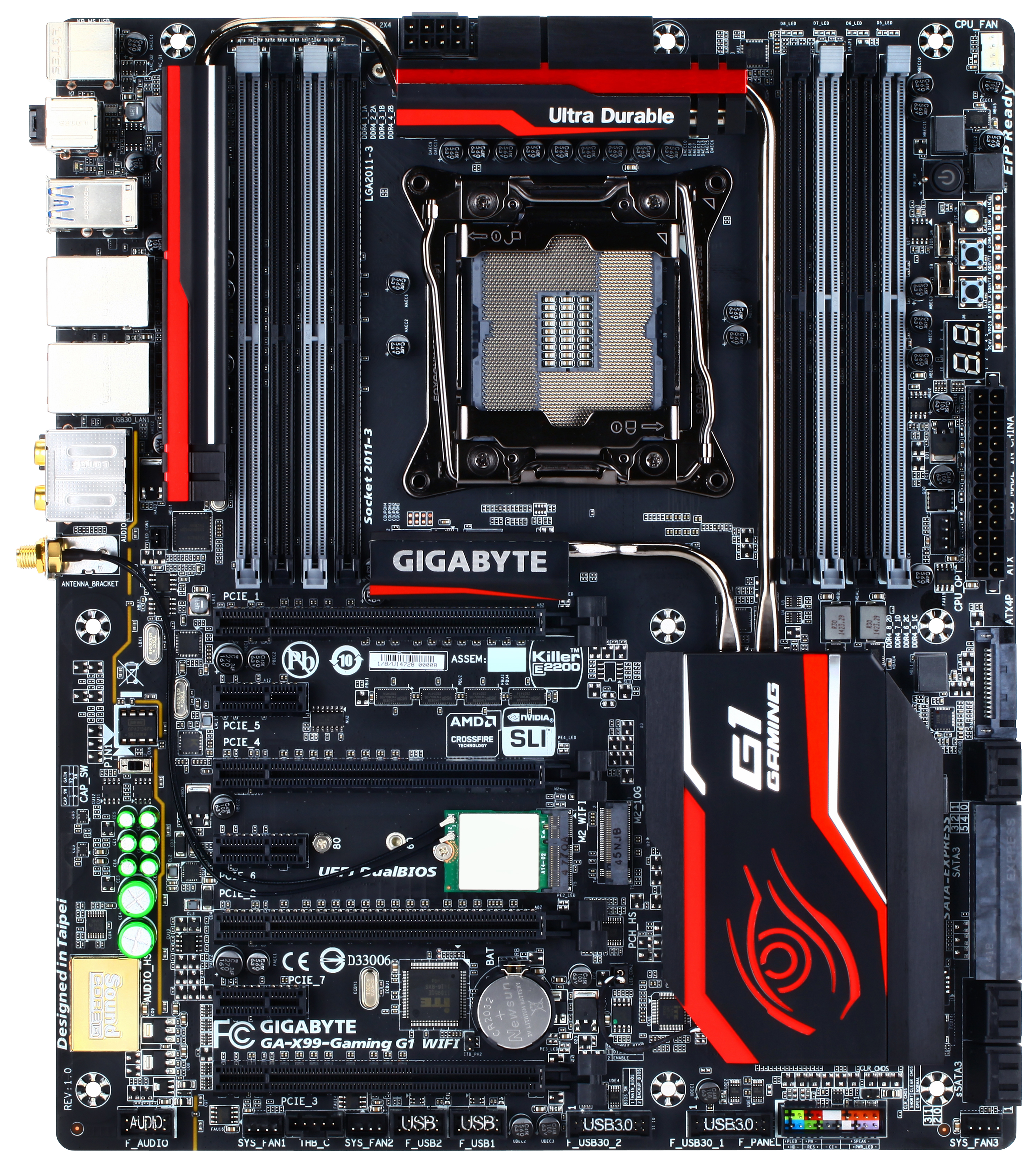
Visual Inspection
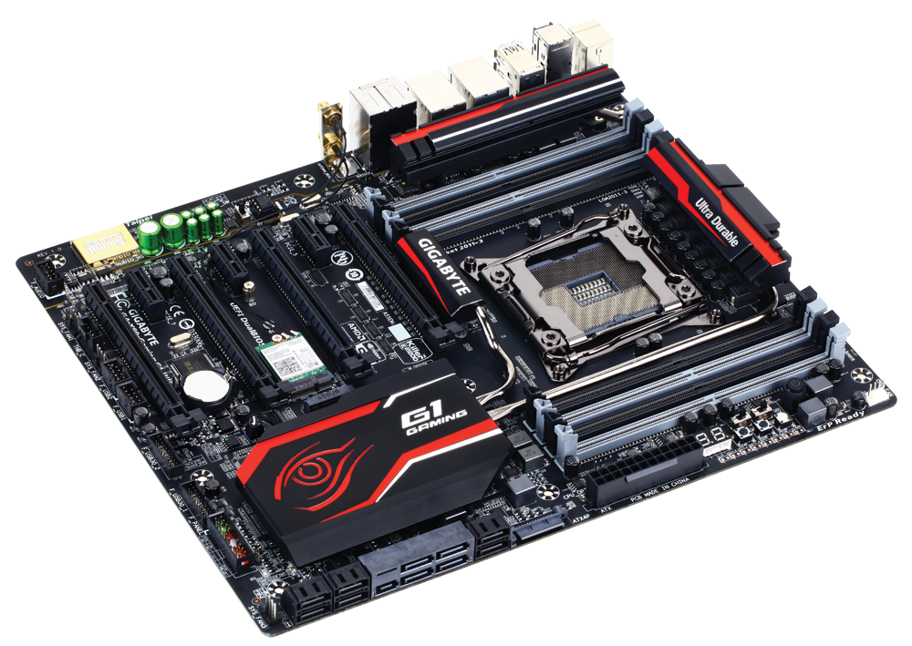
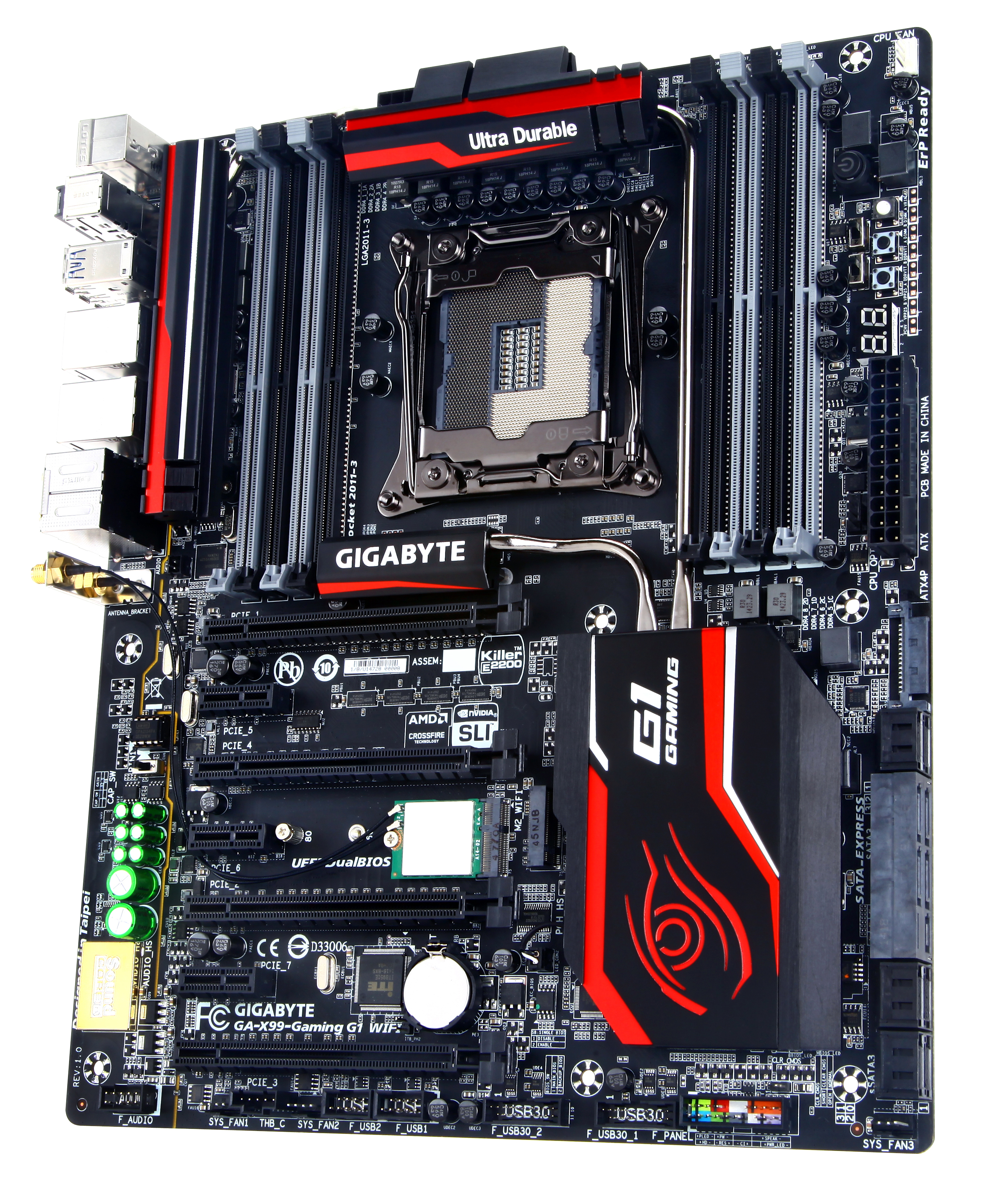
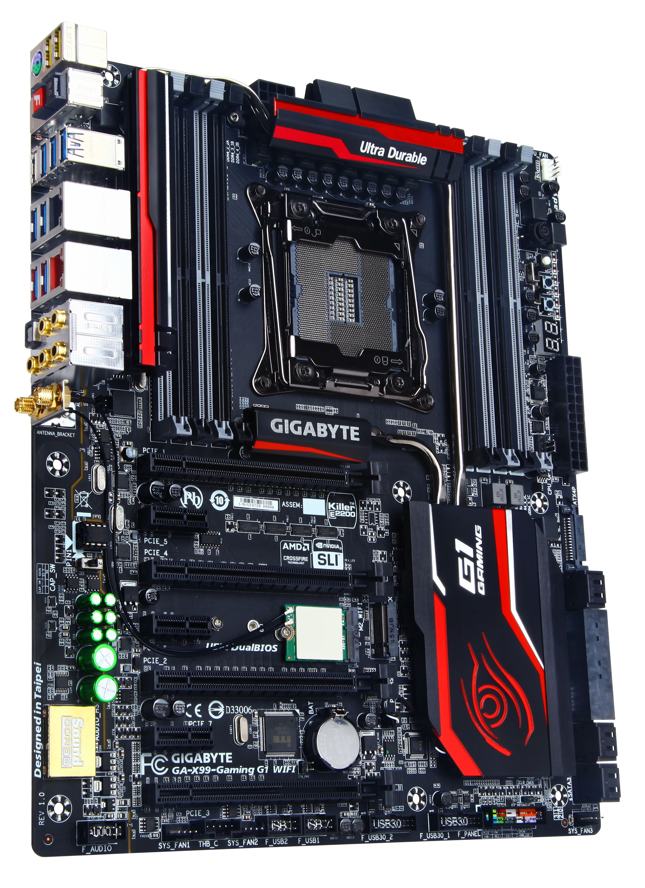
One of the most obvious features to notice when removing the board from the box is the extended heatsink arrangement around the board. This encompasses a section to the left of the socket, the power delivery, the chipset and another section above the PCIe. For high end motherboards I am a fan of this connected heatsink design as it allows more non-IC airflow focused cooling such liquid cooling.
The board is color coded to red and black with grey DRAM slots. While this is bolstered by the red lighting when switched on, the green and gold of the audio section of the motherboard might detract from the overall look. One suggestion here would be for GIGABYTE to look at adding an audio protective plate to continue the red and black Gaming styling.
Alongside the double empty distance screw holes, the socket area is relatively clean with a fine eye to distinguish where the traces are on the motherboard due to the coating applied. The socket itself, like the DRAM slots and PCIe slots, use a 30-micron gold coating to increase resistance to corrosion and other elements that might befoul the connectors. This is 6x the standard amount of gold applied, and 2x most other manufacturer implementations. The socket area has access to only two headers – the four pin CPU fan header in white at the top right and a 4-pin CPU_OPT near the 24-pin power. The board has three other SYS fan headers at the bottom of the board, also all 4-pin.
The top right of the motherboard houses GIGABYTE’s onboard tools for extreme overclockers:
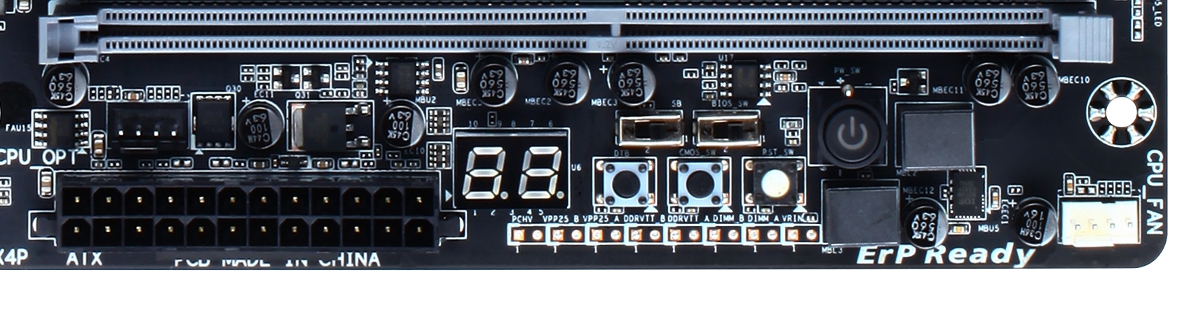
This is a cut down version from the X99-SOC Force, but we still get a power button, a BIOS selection switch, a dual BIOS enabling switch, a reset button, a clear CMOS button, a Direct To BIOS button, voltage check points and a two-digit debug display. As expected there are no frequency adjustment tools here, as buying the Gaming range tends not to lead towards extreme ‘every MHz counts’ arrangements.
Below this we have a SATA power port for extra power to the VGA slots. This is recommended should a user need 3+ PCIe devices that all require extra power. Next we get ten SATA ports, all from the chipset, with the first six being RAID capable and the following four are not due to PCH limitations. In the middle here is a SATA Express slot which shares bandwidth with the SATA ports within as well as the M.2 slot on the motherboard. This means only one set can be used at a time, but there are capable of RST.
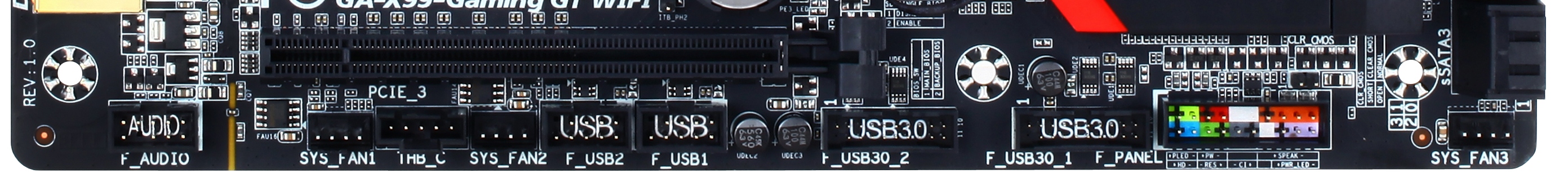
The bottom of the motherboard contains the three aforementioned fan headers as well as two USB 3.0 headers (from the chipset), two USB 2.0 headers, the front panel audio header, the front panel header and a Thunderbolt header.
The audio portion of the motherboard takes the usual AMP-UP styling used on GIGABYTE’s boards with Realtek but this time applied to the Creative Sound Core 3D codec. This means an EM shield for the codec, upgraded filter caps, PCB separation and gold connectors on the rear panel. GIGABYTE has also equipped the board with an upgradeable OP-AMP for users who like to adjust their setup, as well as a Gain Boost switch to implement additional amplification for high impedance headphones.
To the right of the audio in-between the PCIe slots are our M.2 connections, with the WiFi card already preinstalled. The M.2 PCIe SSD slot supports up to PCIe 2.0 x2 from the chipset, with 2242, 2260 and 2280 sized drives.
One of GIGABYTE’s marketing points for the X99-Gaming G1 WIFI is the PCIe layout, and due to additional onboard timing circuitry is using the full 40 PCIe lanes from the motherboard such that:
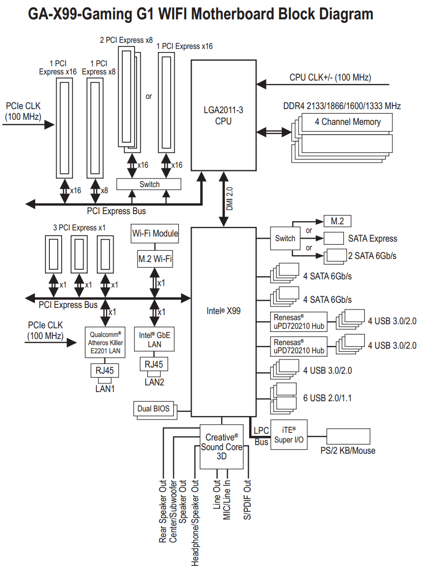
Here the x16/x16/x8 from the CPU is only split on one PCIe 3.0 x16 slot to give PCIe 3.0 x8/x8. GIGABYTE also arranges their PCIe numbering system slightly differently, such that instead of counting one two then three from the top, GPUs should be placed in the order of the slots labeled one-two-three-four. This gives three-way setups a full x16/x16/x8 layout with a 40 PCIe lane CPU, or x16/x8/x4 with the 28 lane CPU. Users with an i7-5820K and tri-SLI setups will therefore have to use PCIe slots one, two and four to get x8/x8/x8.
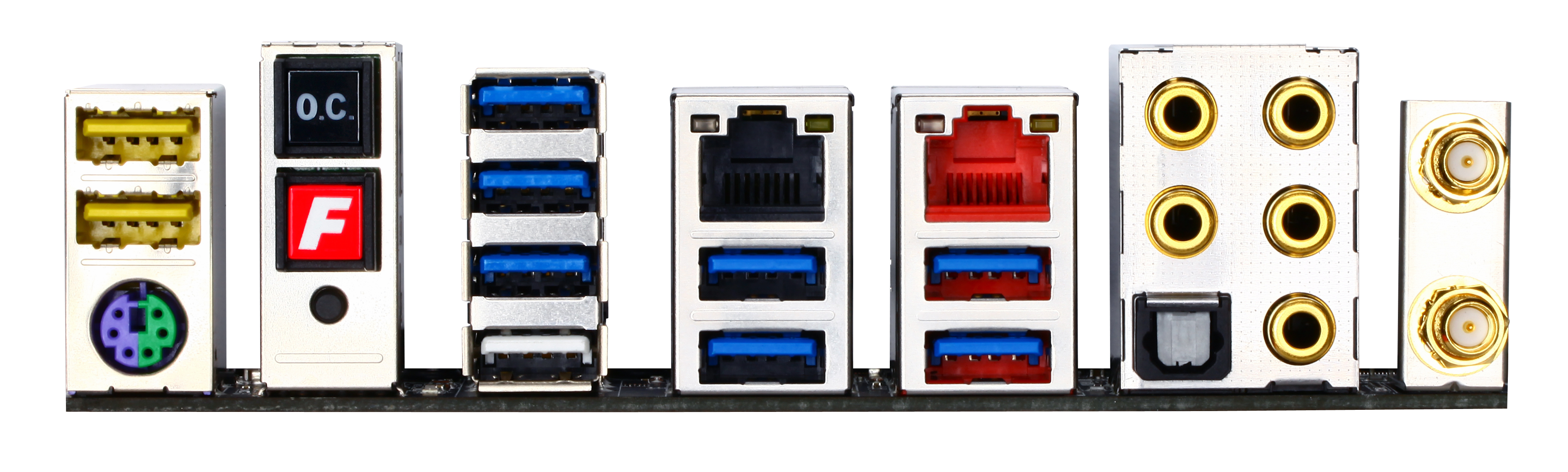
The rear panel features the two USB DAC-UP ports in yellow with a combination PS/2 port underneath. Then comes an auto-OC button, a fast boot button and the ClearCMOS button. The eight USB 3.0 ports on the rear panel are derived from the PCH but come through two Renesas hubs. The white port at the bottom is for GIGABYTE’s Q-Flash Plus system to update the BIOS via a USB stick without DRAM, CPU or a PCIe card installed. We also get dual NICs, one from Intel and one from Killer. The audio jacks are gold plated to reduce corrosion, and we also get the 2T2R antenna connections.
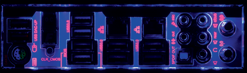
Part of the package is also a UV light based rear IO panel which connects to one of the headers. This can be controlled in software to be on, off, pulse, or react to audio.
Board Features
| GIGABYTE X99-Gaming G1 WIFI | |
| Price | US (Newegg) |
| Size | E-ATX (305mm x 259mm) |
| CPU Interface | LGA2011-3 |
| Chipset | Intel X99 |
| Memory Slots | Eight DDR4 DIMM slots supporting up to 64 GB Support for non-ECC UDIMMs Support for non-ECC RDIMM 1Rx8 Modules Up to Quad Channel, 2133-3000 MHz |
| Video Outputs | None |
| Network Connectivity | Intel I218-V Killer E2201 |
| Onboard Audio | Creative Sound Core 3D |
| Expansion Slots | 2 x PCIe 3.0 x16 2 x PCIe 3.0 x8 3 x PCIe 2.0 x1 |
| Onboard Storage | 6 x SATA 6 Gbps, RAID 0/1/5/10 4 x S_SATA 6 Gbps, no RAID 1 x SATA Express 1 x M.2 PCIe 2.0 x2 |
| USB 3.0 | 2 x Onboard Headers (PCH) 8 x Rear Panel Ports (PCH via Renesas Hubs) |
| Onboard | 10 x SATA Ports 1 x SATA Express 1 x M.2 PCIe 2.0 x2 2 x USB 3.0 Headers 2 x USB 2.0 Headers 5 x Fan Headers Power/Reset Buttons Two-Digit Debug BIOS Switches Direct-To-BIOS Button ClearCMOS Button Voltage Measurement Points Audio Gain Switch Replaceable OP-AMP Thunderbolt Header Front Audio Header Front Panel Header |
| Power Connectors | 1 x 24-pin ATX 1 x 8-pin CPU 1 x SATA for VGA |
| Fan Headers | 1 x CPU (4-pin) 1 x CPU-OPT (4-pin) 3 x SYS (4-pin) |
| IO Panel | 2 x USB 2.0 (with DAC-UP) 8 x USB 3.0 (via Renesas Hubs) Combination PS/2 Port OC Button Fast Boot Button ClearCMOS Button Q-Flash Port (one of the USB 3.0) Intel I218-V Network Port Killer E2201 Network Port Audio Jacks |
| Warranty Period | 3 Years |
| Product Page | Link |


16 Comments
View All Comments
chizow - Thursday, December 18, 2014 - link
Ian, did you have a chance to thoroughly test out OC'ing on this board, and if so, what BIOS revision did you test? I did note you had a few mentions of the auto-OC feature, but I have the Gaming 5 version of this board and I have to say it is one of the hardest I have ever worked with in over a decade of custom builds. From the feedback on various forums including the Tweaktown Gigabyte BIOS thread, it seems this is pretty consistent across all of the Giga X99 boards.Some of the crazy stuff I have seen is:
1) Hard loop on bad OC settings. They have fixed this somewhat with the latest BIOS so it will usually allow you to re-enter the BIOS on a bad boot/OC. Before you had to do some janky things like disconnect all your RAIDed SATA connections or it would halt on POST and prevent you from getting into the BIOS.
2) Early versions of the BIOS did not allow for ANY overclocking. Things have improved gradually, but I have still found this board takes some 0.02-0.03V higher than other boards to achieve similar OCs. For example, an Asus board might only need 1.265V to achieve 4.5GHz, while I need 1.295V to get 4.4GHz stable.
3) Examples of "mostly" stable (ie. apps, games, stress tests) will have no problems in Windows, but they won't allow for wake from S3 Sleep. Adding more voltage allows the PC to wake but somehow the board defaults to its stock speeds, ie. does not retain overclock once it is awake. Restarting will result in the bad OC screen, showing the OC was not completely stable to begin with. Adding more voltage fixes this, but it is a lot of voltage compared to other boards.
4) This board does not like RAM speeds above the stock 2133MHz. Very disappointing, I'm using 2666MHz Corsair with XMP and this board will run, but again, will not wake from sleep or retain OC settings at higher RAM speeds. I know this is not official JEDEC spec but other boards do not have a problem with this at all. I have not yet tried to use manual settings for the timings, but I really shouldn't have to, that's what XMP is for.
5) Board would not boot at all with the auxiliary 4-pin molex connector attached.
I got this board for a great price (free), so I can't complain too much, but if I had spent my own money I would be very upset with it. I've had good experiences with Gigabyte in the past with their Z87X-UD4 and the X58-UD3R before that, but this board has been a big disappointment. There's probably at least 4-5 bugs I encountered that would've been a showstopper for a less experienced builder, so Gigabyte really needs to clean up their act, imo, because no one should have to jump through the hoops I went through to get this board working with a decent overclock.
That said, this board is probably fine for anyone who is planning to run it bone stock clocks.
BoredTech - Friday, December 25, 2015 - link
This is a game board, the oc board is the SOC from them.angrypatm - Thursday, December 18, 2014 - link
It's funny how some people are so concerned about the looks and color of a mobo, I guess they wouldn't buy it if it was brown and purple.littlebitstrouds - Friday, December 19, 2014 - link
Awe, I miss DFI boards.gammaray - Saturday, December 20, 2014 - link
i don't get it, why invest in a X99 board with a 500$ cpu when a z87 coupled with a 4770 perform just as well?Zan Lynx - Saturday, January 17, 2015 - link
Because "performs just as well" is not true? It might or it might not, but that depends on the application you're using. I'm running a 5960x overclocked to 4.1 GHz and I guarantee it will crush a 4770 like a bug.